-
"Dam-Drum is a handheld drum machine and sequencer with four unique sounds selected by Dam-Funk. This is a collaboration with Dam and Bleep Labs, who designed and built the drum in Austin, Texas." And that right there is your future of music merch: support your favourite artist by purchasing custom hardware with their sounds in. They only made 100, because exclusivity (or is it because longer runs would be painful to make), but it's got lovely packaging, and is surprisingly functional.
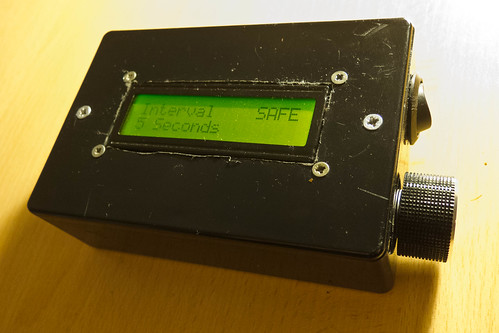
The black box above is an intervalometer to work with Nikon cameras (specifically, any cameras that work with the cheap ML-L3 remote). It has two external controls: a power switch and a knob. You rotate the knob to choose the interval period on the screen, and click it in to arm the intervalometer. Clicking it again and briefly holding it until the screen lights will disable it.
Which sounds simple enough, I suppose. I mean, it’s simple to explain. But when I began, I wasn’t even sure if I’d be able to make this – which was part of the adventure.
My commit messages tell me I’ve been working on it for over a year. It’s not, to be honest, a year-long project; it’s just how it came about, scraped together in moments between work, and I wanted to write some notes on the project – both what it is, and what I learned from it.
The Design
Like many of my technically-savvy peers, I had an Arduino in a desk drawer. I’d used it for more than just making an LED blink – a few little experiments in serial communication – but I’d not exactly exploited its full capabilities.
One day, I had a thought: I wanted to experiment with time-lapse photography, and had a small IR remote for my camera. Perhaps I could make something computer-controller to enable this? Not a full-size computer, that’d be ridiculous. But I could perhaps make something with a small microcontroller – like my Arduino – wired into a spare remote, firing regularly.
That smelled like it was within my reach: a little user interface and a timer.
So I refined the design in my head. In the end, I had a few goals for the project:
- I wanted to use a rotary encoder as the interface: it seemed much more natural than stabbing up and down with buttons.
- I wanted to use a small LCD screen in the project: I’d never worked with one, and it seemed like the simplest UI for the project. Also, there was a fun design challenge in fitting clear UI into 16×2 characters.
And that seemed like a starting point.
Building the First Version
There were four unknowns in the project, which roughly corresponded to the four milestones in building it:
- working with the LCD screen
- working with the rotary encoder
- interfacing with the camera
- writing a timer routine
I began at the top. I chose to work with a Serial interface to the LCD – one pin instead of seven seemed like a good trade-off, and it was a tiny bit easier to get started with. Quite soon, I had a UI displaying on the screen:
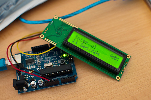
This felt like a huge leap. Somehow, making rudimentary computer graphics in tools like Logo or Processing had never captured my imagination – perhaps because I felt I ought to be able to do that. Working in a medium I was very unfamiliar with as a developer (but saw every day in my life) and producing output felt strangely empowering.
Of course, it was made much easier by the Arduino ecosystem, which is ideally suited to glue-programmers like myself. The SerLCD library did a lot of the heavy lifting; I just had to work on the implementation, and some details around making sure I put enough pauses in the serial routine.
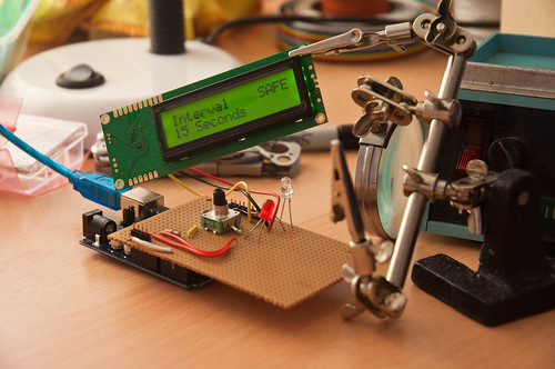
Next, I worked on the encoder. This, again, was enabled by other people’s code. Rotary encoders aren’t like knobs – they spin forever, and as they pass a pair of contacts, emit Gray code from a pair of pins. You just have to read that code as it passes a pair of pins, and translate it into up/down signals. It wasn’t long – again, thanks to the magic of copy and paste, primarily – before I had the encoder being read.
I then added some detail to its implementation, where setting the timer past 90 seconds switches the device into minutes, which increment by 1, until it reaches 15 minutes. Why 15? It’s the maximum length of time my camera would stay on without any IR input before it goes to sleep.
Finally, we just need to rig up the IR interface. I was, when I began, ready to dismantle an ML-L3 – but it turned out I didn’t need to go that far.
There’s already an Arduino library for that exact functionality. NikonIRControl takes a single IR LED on a pin, and sends it the same sequence of pulses as the ML-L3 does. So that ended up being fixed in software, rather than hardware.
(In the final version, I replaced it with MultiCameraIRControl, in part because it’s now much easier to make this work with many brands of camera).
Along with the hardware, there was a bunch of code to be written. This was mostly straightforward, although finding the best way to write timing routines was the most complex part of it, and in the end, I relied on the TimedAction library, which abstracts a lot of what I’d tried writing longhand out. The other thing I discovered was the ability to compile multiple files at once into an Arduino sketch – available through tabs in the IDE. This helped a lot with clarity.
Really, though, the code is a lot of other people’s libraries or examples, all glued together with some UI and specific functionality on my part. That is the sort of code I end up doing a lot of: gluing other things together.
After a few months of the odd evening here and there, I had the whole thing working on a breadboard. The next thing to consider was packaging it up. I made a small shield out of stripboard and mounted it on top of my Arduino mini: a connector jack for the LCD, the encoder and LED soldered into the stripboard, and a battery pack to prove that the USB cable wasn’t doing anything.

That was the first working version. I put a short video on Vimeo. Later in the year, I’d take it to Cornwall with me. There, I shot this 30-minute timelapse:
That really proved it worked: not just the electronics, or the software, but the intent. The goal was not making electronics; the goal was making a timelapse video, which the electronics enabled. And here we were: a timelapse video.
Of course, it wasn’t finished.
My friend Matt Brown saw an early verison of this, and said that it needed to be in some kind of sturdy, industrial black box. And he’s right, really. Something rigged up on your desk on a breadboard is nice, but it’s not finished. Frankly, that dangle of a shield hanging from my lens was nowhere near finished either.
There is value in just doing something, but there is also real value in finishing it. That doesn’t mean selling it, or productizing it, or anything as over-the-top like that. Just get it into a stage where somebody else might recognize it for a thing.
So I started thinking about how to package it, because that would be what really made it a thing, and not just a tangle of wires.
Packaging
The limiting factor on packaging was the LCD screen. I was using a Serial LCD, and the serial componentry was hanging off one edge, extending the length of its PCB. I should have probably used a seven-pin LCD interface, but instead stuck to the serial interface. I took a regular seven-pin LCD, and used this Sparkfun Serial Backpack to convert it to serial whilst taking up less space.
Next, I decided there was no point running it from a full-size Arduino, so bought a Pro Mini, and set about re-installing the code there.
Of course, that meant flashing the Pro Mini, and rigging the whole circuit up on a breadboard, checking it still worked, before moving to a custom circuit.
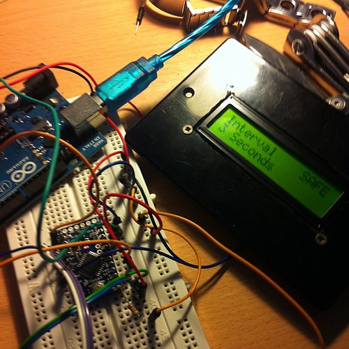
With that done, I made a stripboard for it. (Yes, I keep using stripboard, because it works for me. I don’t know much about PCBs or Eagle, and that would mean this thing was never going to get finished). I would mount the Pro Mini in the middle of this stripboard, and then attach components around it, breaking the tracks where appropriate, to make a stripped-down board.
Crucially, I didn’t directly solder anything other than the battery jack leads. Rather, I put female header sockets onto the board, for the Pro Mini and all the components. Then, I attached the components with hires ending in male headers. That way, I could remove/install componentry easily, and also remove the Pro Mini easily to reflash it with new software. This turned out to be one of my smarter moves.
Finally, there was the matter of the box. Probably my weakest point: I am somewhat clumsy and useless with my hands. Also, I don’t really have any workshop facilities, so drilled the holes for power and encoder, along with the hole for the LCD, with files and a Dremel-a-like. This made a horrendous, ragged mess, and I envy people with CNC facilities or a decent mill. I did use my Dad’s workshop to mount the LCD, which means it at least got some counter-sunk, well drilled holes. Oh, for a pillar drill.
Finally, I just had to piece it together, testing the final version of the code, and plugging components in one at once.
It is strange to say “remarkably, everything worked” so much, but hardware is so strange and fincikity I always expect it not to. Also: I was aware throughout how out of my depth I was, and yet I always bobbed back to the surface.
Squeezing the box shut, the serial backpack on the screen impinged a bit on space, but careful board and battery placement made it shut. And that was that: a working, solid box, that did one thing, with software I’d written and hardware I’d made. More to the point: it was finished.
Finishing and Thingness
This project taught me a few values.
I discovered with this project is the way that Arduino reminds me of Rails: it directly values productivity of the designer/developer, and you pay for that convenience. This project could have been made out of discrete components, or out of a much simpler AVR chip, but it’d have taken me a lot of knowledge and experience. I pushed all the complexity into software, and embraced the Arduino platform. So it may have cost me £20 for the Uno, and about that for the final Pro Mini, as opposed to a few pounds for a bare microcontroller – but I saved myself effort. Still, it’s worth remembering that these solutions are in turn made out of other existing hardware, and that one day, that might be a better solution.
The project taught me the value of thingness: of completing something so that it’s an artefact other people can recognise and identify. The box-with-a-lid is a huge part of that. It stops it being a bunch of wires, something I explain as “an Arduino doing X”, and it becomes an Intervalometer. It becomes a thing.
And finishing is hard. You think software, or electronics is hard? Making a box chewed me up and spat me out. It’s not too hard to make the ragged, ugly holes I did, but gosh, I’d love the precision and experience to not have scratches from skittering milling bits, or the ragged holes around the LCD. Not to mention the entire rebuild of the project necessary to get it small enough to fit into aforementioned box. It reminded me, in the tiniest way, of Nick Foster’s lovely post about the difficulties of making:
It’s now simple for a couple of fairly inexperienced guys to feasibly produce products for sale, which is fantastic, but let’s take a critical look at a few of these products. How many of you have invested in a cool thing on Kickstarter only to receive constant emails about how expensive tooling is, or how hard it is to source PSU’s, or how the team massively under-budgeted the production? There have been many projects which simply ground to a halt because the Matter Battle was just too tough, before we even get into the debating the dubious legal position of these devices (CE mark anyone?)
Foster is talking about manufactured products, of course, which I’m not; I’m still much earlier along the curve. But Matt Brown’s point, a year ago, to make sure I completed it, not just leaving a pile of wires sticking out of a breadboard, was a challenge I felt it worth rising to – and I’m glad I did.
Perhaps most importantly, though, it reminded me of the huge value of making something you saw in your head. It’s vastly rewarding to make an idea that you originated; to solve a problem that you yourself had. I’ve always found that I learn new things better when I have a reason to. Every programming language I’ve tried to learn without something I myself wanted to build with it – I got nowhere. The second I have an itch I need to scratch, I’ll bat through tutorials and understand them, not to mention start trying to implement that thing as soon as I can.
This, I think, is hugely important. It’s why I think an important part of learning to code – for kids, or for adults – is achieving something you wanted – or needed – to do. It’s vital to understand that making, in software, hardware, or materials, is something you do unprompted, to solve problems, and not always knowing where the journey will take you. You don’t just implement rote linked lists, or bubble sorts, or debounce circuits; learning from examples is important, and often all one can do to begin with, but it’s not what the work is about. To learn to make things, you have to Make your own Things. You have to travel a complete path. It doesn’t just make the end more rewarding: it makes the whole journey more rewarding.
I wonder if that’s why a lot of Arduinos are in desk drawers, an LED wedged into pin 13: the platform is exciting and interesting, but there was never an itch. When that itch arises, take that board out of the drawer and scratch it. It is difficult, but it is within your abilities, and you will learn a lot. I did.
-
Simple dynamic site generator with standardised templating tools: certainly looks nice for building those early-stage prototypes before you need a full backend.
-
"The history of switching power supplies turns out to be pretty interesting." It really does: long, fascinating post about a history of AC-DC conversion and how new technologies affected it.
-
"Remote terminal application that allows roaming, supports intermittent connectivity, and provides intelligent local echo and line editing of user keystrokes." As recommended by Matthew Somerville. Looks useful!
-
"Modern digital cameras capture gobs of parsable metadata about photos such as the camera's settings, the location of the photo, the date, and time, but they don't output any information about the content of the photo. The Descriptive Camera only outputs the metadata about the content." Lovely: a camera powered by Mechanical Turk.
-
"There’s still a smell of bullshit to almost every videogame story I read, even as it’s advanced to a very high level being in The New Yorker and The New York Times Magazine. To me it derives from this politeness about the thing that’s experienced. In literary criticism there are really cutting deconstructions of things that are inadequate—Nabokov talking about what a fraud and charlatan Faulkner was—but there’s this really intelligent, but painfully milquetoast, quality to the way we appreciate games. It’s a reflection of how partially engaged we are with each one. We consider games primarily as ideas, rather than actual evolving relationships that we’ve had over time." Yeah, that. I enjoyed this discussion: I'm pretty sure you don't have to finish games to review them. Then again: I also think writing about games six months after they came out is way more interesting than trying to hammer through something to fit into a review cycle.
-
Oooh, the Shruthi got an upgrade: not just white PCBs, but an interesting new filter board. Seriously tempted by one of these.
-
"The hackable, digital synth": cheap, build-your-own virtual analogue. Interesting.
-
"I've been working on a sketch wherein some data is downloaded from an HTTP server and is then processed on the Arduino (printed, as it happens, but I don't think that's important). In my original sketches, I was occasionally seeing transfers fail midway through." James is running into issues that might be relevant to me.
-
"The Shruthi-1 is a hybrid digital/analog monosynth. Its hardware design is deceptively simple, but the sonic range is wide: sometimes grungily digital like a PPG-Wave, fat and funky like a SH-101, videogame-y like a Commodore 64, weird and warm like an ESQ-1 ; but more often than not, truly original." Looks nice, not expensive at all.
Nikon D-Series Intervalometer
17 May 2011
So, here’s a thing I’m making.
My Nikon D90 can be triggered by the cheap ML-L3 IR remote. It costs about £15. You point it at the camera, push the button, and it takes a picture.
This remote works with everything from the D90 down (so, towards the D3100/D40 end of the line).
What these cameras don’t have built in, however, is an intervalometer: a timer that will make the camera take a picture every n seconds or minutes. (The D300 and up (and, I believe, the new D7000) have a built-in intervalometer.)
I thought it might be interesting to build one. The project had a few criteria:
- It couldn’t be hard-wired to a computer. It had to be a stand-alone, battery-powered device
- It had to have a half-decent way of controlling it; ideally, not just stabbing at buttons.
- I wanted it to have a 16×2 LCD screen, mainly because I wanted to both design for that constraint, and work out how to control said screen
- Ideally, it wouldn’t require taking apart an ML-L3 remote to build.
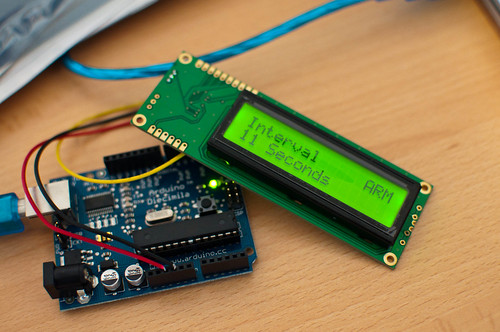
Here’s where we are:
End-to-end: it works. Note that I said “making” earlier, though: it’s still not finished, because it’s not packaged. And whilst packaging is difficult, I think that’s what’ll make it feel finished for me: a black box I can easily take into the field.
You turn it on, rotate an encoder to set a time, and click the encoder in to arm it. Hold the encoder to disarm. The time varies from 1 second to 15 minutes – after 90 seconds, it increases in minute chunks. (15 minutes is the maximum time the D90 will stay on before powering down).
Most people ask me why it says “SAFE” and “ARM”. Well, it sounds a bit threatening, but I genuinely believed that OFF and ON were inaccurate, in that the device is “on” if the screen’s on. So I was just referring to the state of the timer. And something that fitted into four characters would work well with the layout of the screen I’d chosen.
How it works
There’s very little componentry here, but each section of the Intervalometer was a neat little thing to learn on its own.
First, the IR trigger itself. Nikon’s IR remote is relatively simple: a button, some circuitry, and an IR LED. Pushing the button doesn’t just light up the IR LED; it fires a very short “coded” burst of light, so that the only thing it’ll trigger will be a Nikon camera.
Fortunately for our needs, there’s an Arduino library called NikonIRControl, which emulates that coded burst in software – so a single command will send the appropriate burst to a digital output pin. That’s our IR trigger sorted, and all we’ve had to buy is an IR led. Which feels better – and cheaper – than just soldering two wires to a Nikon remote.
The screen is a 16×2 LCD, with a serial “backpack” pre-attached. That means I can just send serial data to it over a single wire, which again, keeps the number of wires from the Arduino down. I’m using the NewSoftSerial library to talk to it, which makes life easy.
The main controller is a quadrature rotary encoder with a push-switch in it. The switch is easily read, like any momentary push-switch on an Arduino. The encoder is a little trickier, because it’s encoded. In the end, I read it off an interrupt, using code from this page – and then smoothed it out a bit by making it only read every other click.
Finally, there’s just the case of the timer. Timers are a bit more fiddly than I’d have liked. You can’t just use delay, because that delays all code on the chip. I tried doing various things including counting milliseconds, but in the end, relied on the TimedAction library, which works well enough, and does a similar thing without my broken code.
Once each piece was in place and working, it was just a case of pulling it all together. The code – which is available on Github – is broken down into a series of files, pretty much one for each section of the project. I found this much easier to manage than the tyranny of One Big File.
For piecing the hardware together, I built a simple “shield” out of a piece of Veroboard. I got a lot of laughs when I said I was using veroboard, but it worked very well for me. With some headers soldered in, it was quite easy to line it up with the Arduino – making it easily changed, but also swappable. The usual electronics-debugging issues aside, this went fairly smoothly, and it only took a battery pack to give me a portable – if fragile – working intervalometer.
What’s next? Obviously, packaging it up – something sturdy and black, with an obvious power switch and that big knob. I was considering moving it to an Arduino Mini, for size reasons, but am not sure I can face more electronics debugging. Similarly, I’m not sure I’ll build a dedicated PCB or anything like that, yet.
But: if I can get this lot into a box, that’ll be good. Also: I should take some timelapses with it.
So whilst it’s not what I would call “finished”, it is an end-to-end demo – and that feels like good enough to share with the world.
(And, of course: if you’d like to use – or build on – my code, you’re more than welcome to.)
-
"
hen I finally got around to playing Portal, I was a bit surprised at how much the Internet loved the companion cube. Sure, the cube is pretty great, but in my mind it pales in comparison to the turrets, the real scene-stealers of the game. In fact, they inspired a Veruca Salt-esque covetousness in me. I wanted one. Badly. And, of course, it just wouldn’t be the same if it didn’t talk…" I had forgotten how much I loved the turret dialogue. You monster.
-
"It's very simple. If there are more than five bikes at one of these bike stations the relevant LED comes on. It's a glanceable guide to which way to walk when we head out. It's going on the wall by the door. No need to reach for a device, launch an app and navigate to our favourites." Situated hardware. Very good.
-
Matt Brown and Mark Slater, writing about music and things. Looks set to be like a cracking little blog.
-
Reviews of Phill Niblock's "Touch Three": drones created by stripping out attack/release/breath sounds from acoustic performers, and then gluing them together. What we're listening to right now, too. (It is better than that description makes it sound).
-
This is, in fact, the most successful rotary encoder code I've found to date.
-
Excellent summary of what happened on the Yaroze – and a quest to track down all the released Yaroze titles.
-
Jason Rohrer's recursive shooter, which I must pick up at some point.
-
Microcontrolled Lego printer, running off some kind of postscript driver, I guess. Properly awesome – and, of course, the most important thing is all the little chaps that keep it working.
-
Nikon IR intervalometer, hooked up to an Arduino, without even needing another remote. Definitely interested in building one of these.