So, here’s a thing I’m making.
My Nikon D90 can be triggered by the cheap ML-L3 IR remote. It costs about £15. You point it at the camera, push the button, and it takes a picture.
This remote works with everything from the D90 down (so, towards the D3100/D40 end of the line).
What these cameras don’t have built in, however, is an intervalometer: a timer that will make the camera take a picture every n seconds or minutes. (The D300 and up (and, I believe, the new D7000) have a built-in intervalometer.)
I thought it might be interesting to build one. The project had a few criteria:
- It couldn’t be hard-wired to a computer. It had to be a stand-alone, battery-powered device
- It had to have a half-decent way of controlling it; ideally, not just stabbing at buttons.
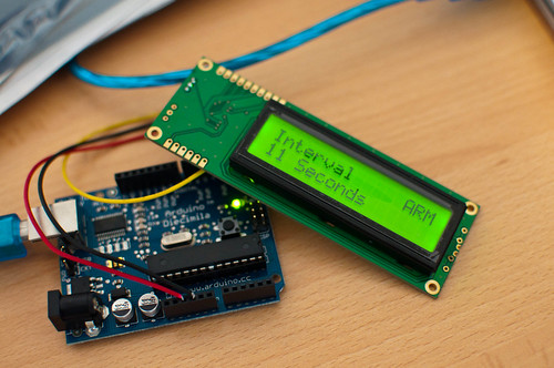
- I wanted it to have a 16×2 LCD screen, mainly because I wanted to both design for that constraint, and work out how to control said screen
- Ideally, it wouldn’t require taking apart an ML-L3 remote to build.
Here’s where we are:
End-to-end: it works. Note that I said “making” earlier, though: it’s still not finished, because it’s not packaged. And whilst packaging is difficult, I think that’s what’ll make it feel finished for me: a black box I can easily take into the field.
You turn it on, rotate an encoder to set a time, and click the encoder in to arm it. Hold the encoder to disarm. The time varies from 1 second to 15 minutes – after 90 seconds, it increases in minute chunks. (15 minutes is the maximum time the D90 will stay on before powering down).
Most people ask me why it says “SAFE” and “ARM”. Well, it sounds a bit threatening, but I genuinely believed that OFF and ON were inaccurate, in that the device is “on” if the screen’s on. So I was just referring to the state of the timer. And something that fitted into four characters would work well with the layout of the screen I’d chosen.
How it works
There’s very little componentry here, but each section of the Intervalometer was a neat little thing to learn on its own.
First, the IR trigger itself. Nikon’s IR remote is relatively simple: a button, some circuitry, and an IR LED. Pushing the button doesn’t just light up the IR LED; it fires a very short “coded” burst of light, so that the only thing it’ll trigger will be a Nikon camera.
Fortunately for our needs, there’s an Arduino library called NikonIRControl, which emulates that coded burst in software – so a single command will send the appropriate burst to a digital output pin. That’s our IR trigger sorted, and all we’ve had to buy is an IR led. Which feels better – and cheaper – than just soldering two wires to a Nikon remote.
The screen is a 16×2 LCD, with a serial “backpack” pre-attached. That means I can just send serial data to it over a single wire, which again, keeps the number of wires from the Arduino down. I’m using the NewSoftSerial library to talk to it, which makes life easy.
The main controller is a quadrature rotary encoder with a push-switch in it. The switch is easily read, like any momentary push-switch on an Arduino. The encoder is a little trickier, because it’s encoded. In the end, I read it off an interrupt, using code from this page – and then smoothed it out a bit by making it only read every other click.
Finally, there’s just the case of the timer. Timers are a bit more fiddly than I’d have liked. You can’t just use delay, because that delays all code on the chip. I tried doing various things including counting milliseconds, but in the end, relied on the TimedAction library, which works well enough, and does a similar thing without my broken code.
Once each piece was in place and working, it was just a case of pulling it all together. The code – which is available on Github – is broken down into a series of files, pretty much one for each section of the project. I found this much easier to manage than the tyranny of One Big File.
For piecing the hardware together, I built a simple “shield” out of a piece of Veroboard. I got a lot of laughs when I said I was using veroboard, but it worked very well for me. With some headers soldered in, it was quite easy to line it up with the Arduino – making it easily changed, but also swappable. The usual electronics-debugging issues aside, this went fairly smoothly, and it only took a battery pack to give me a portable – if fragile – working intervalometer.
What’s next? Obviously, packaging it up – something sturdy and black, with an obvious power switch and that big knob. I was considering moving it to an Arduino Mini, for size reasons, but am not sure I can face more electronics debugging. Similarly, I’m not sure I’ll build a dedicated PCB or anything like that, yet.
But: if I can get this lot into a box, that’ll be good. Also: I should take some timelapses with it.
So whilst it’s not what I would call “finished”, it is an end-to-end demo – and that feels like good enough to share with the world.
(And, of course: if you’d like to use – or build on – my code, you’re more than welcome to.)